Resistance, Reactance, Permeability and Permittivity
Posted: Thu Jun 28, 2018 10:45 am
Since my reply to Horace triggered a new understanding of these concepts, I thought I would start a separate topic on it in the EE forum. (Click on the ↑ after "Horace wrote" to read the original topic.)
I treat quaternions differently, because I do not transform the angular velocity into a 2D, linear one, so I only need a 3-axis representation (not 4, as you'll find with regular math). As described elsewhere, linear motion is a translation along an axis, whereas angular motion is a twist of an axis.
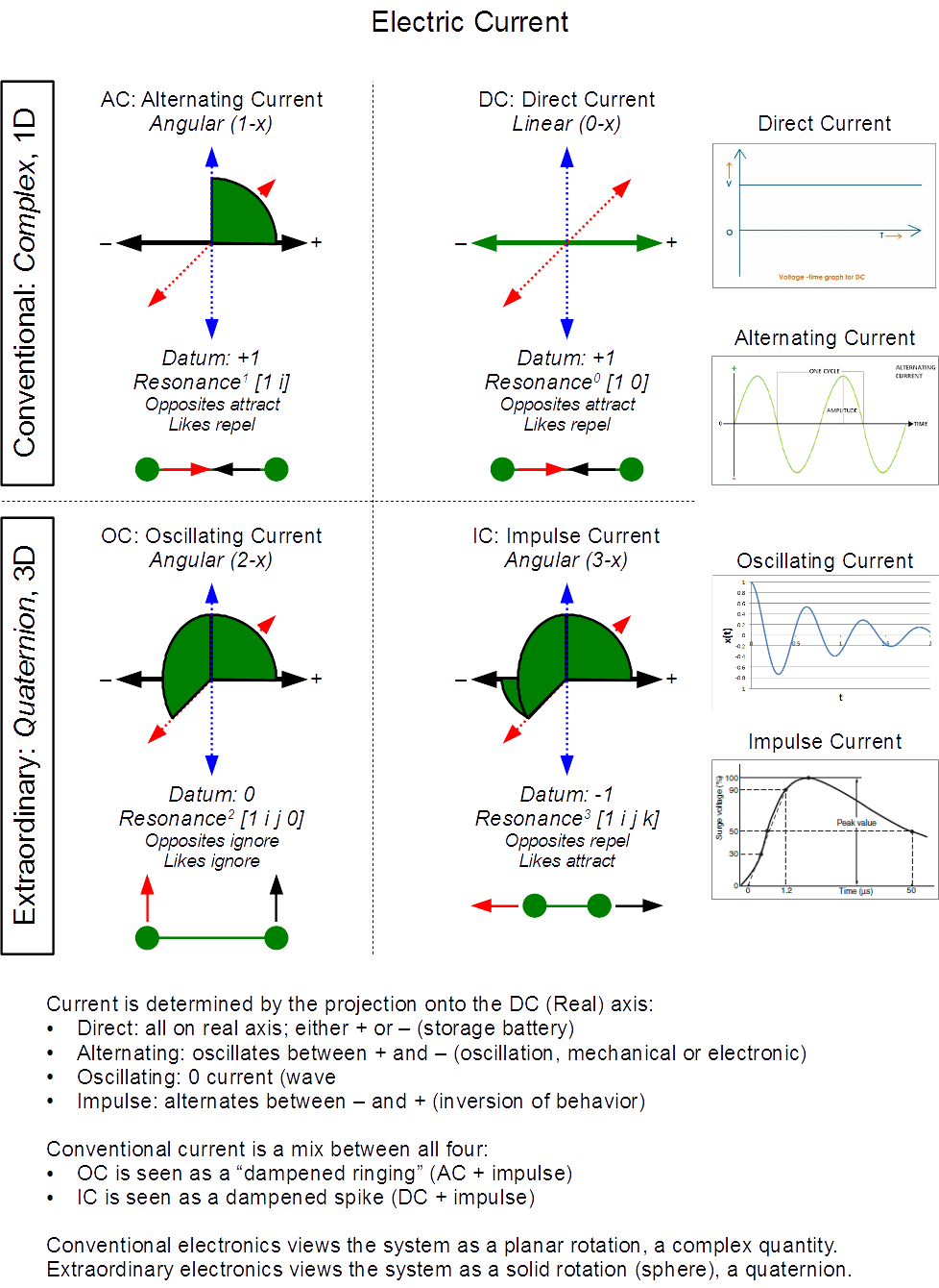
The real axis represents the linear motion of electric current and resistance/conductance, which is analogous to the "progression of the natural reference system" as it always moves at the speed of light, as electric current does. Resistance does not change this speed... the current still flows at c, like the progression does.
The other two axes are used as poles for the angular motion of reactance, the blue is for the typical "j" axis of alternating current, and the red from Steinmetz's work on impulse and oscillating currents. So to get a typical impedance, you have a resistance (radial length) and reactance (angle)--the complex number. The three planes of rotation then form Larson's concept of "speed ranges," of which we stick with the low-speed (1-x) range of DC and AC.
Odd thing about these speed ranges is that low speed and ultra-high speed (3-x) are based in clock time--they have a displacement along the real, DC axis, but intermediate speed (2-x) does not. Intermediate speeds are always at zero on the DC axis, meaning the effect would appear instantaneous, as it occurs without a change in time.
And I just realized something... the red and blue axes must also have a resistance component (translational at the speed of light), due to the symmetry constraints of the RS. And that would infer that capacitance and inductance are the same thing, but from two, reciprocal perspectives... that means the "squished flat" graph-paper form of complex numbers may be incorrectly representing the reactance relationships--being a projection, rather than a 3D structure.
My thought here is that capacitance, having negative reactance, is not in the 1-x range (as complex quantities put it), but in the 3-x range, with only inductance in the 1-x range. Both are time-dependent angular velocities, but would be orthogonal and out of phase by 90°, which may explain the leading-lagging current of impedance.
That would infer that the "resistance" on the blue and red axes would be an indirectly observable quantity--something similar to resistance but nonlocal. If inductive is 1-x, that would make the blue axis permeability and the red axis (3-x), permittivity. A common resistance acts like a membrane, limiting flow through it. Both permeability and permittivity do the same. I will explore this further.
I am no longer using the linear, "graph paper" approach to impedance, but have taken it into another dimension (literally), based on a quaternion rather than complex quantity (see: Extraordinary Electric Current), in which I treat resistance as "real" (linear) and reactance as "imaginary" (angular)--but as a quaternion, not a complex quantity.
I treat quaternions differently, because I do not transform the angular velocity into a 2D, linear one, so I only need a 3-axis representation (not 4, as you'll find with regular math). As described elsewhere, linear motion is a translation along an axis, whereas angular motion is a twist of an axis.
The real axis represents the linear motion of electric current and resistance/conductance, which is analogous to the "progression of the natural reference system" as it always moves at the speed of light, as electric current does. Resistance does not change this speed... the current still flows at c, like the progression does.
The other two axes are used as poles for the angular motion of reactance, the blue is for the typical "j" axis of alternating current, and the red from Steinmetz's work on impulse and oscillating currents. So to get a typical impedance, you have a resistance (radial length) and reactance (angle)--the complex number. The three planes of rotation then form Larson's concept of "speed ranges," of which we stick with the low-speed (1-x) range of DC and AC.
Odd thing about these speed ranges is that low speed and ultra-high speed (3-x) are based in clock time--they have a displacement along the real, DC axis, but intermediate speed (2-x) does not. Intermediate speeds are always at zero on the DC axis, meaning the effect would appear instantaneous, as it occurs without a change in time.
And I just realized something... the red and blue axes must also have a resistance component (translational at the speed of light), due to the symmetry constraints of the RS. And that would infer that capacitance and inductance are the same thing, but from two, reciprocal perspectives... that means the "squished flat" graph-paper form of complex numbers may be incorrectly representing the reactance relationships--being a projection, rather than a 3D structure.
My thought here is that capacitance, having negative reactance, is not in the 1-x range (as complex quantities put it), but in the 3-x range, with only inductance in the 1-x range. Both are time-dependent angular velocities, but would be orthogonal and out of phase by 90°, which may explain the leading-lagging current of impedance.
That would infer that the "resistance" on the blue and red axes would be an indirectly observable quantity--something similar to resistance but nonlocal. If inductive is 1-x, that would make the blue axis permeability and the red axis (3-x), permittivity. A common resistance acts like a membrane, limiting flow through it. Both permeability and permittivity do the same. I will explore this further.